Categories
Mechanical Correction Method of Laser Cutting Machine
Long-term operation may cause laser cutting machines to suffer mechanical displacement and reduced cutting precision. This guide details three core correction methods: guide rail parallelism calibration, worktable horizontal leveling, and diagonal squareness adjustment. Follow these step-by-step operations to eliminate errors, restore machine accuracy, and ensure consistent high-quality cutting results.
Mar 7th,2019
43 Views
Laser cutting machines have become one of the fastest-growing metal cutting equipment in recent years and are widely used in many industries. However, after long-term operation, the mechanical system may develop certain displacements, which will reduce cutting quality and equipment accuracy.
Therefore, regular mechanical system correction is especially important. The accuracy of mechanical correction will directly affect the final cutting result
1. Guide Rail Parallelism and Laser Path Correction
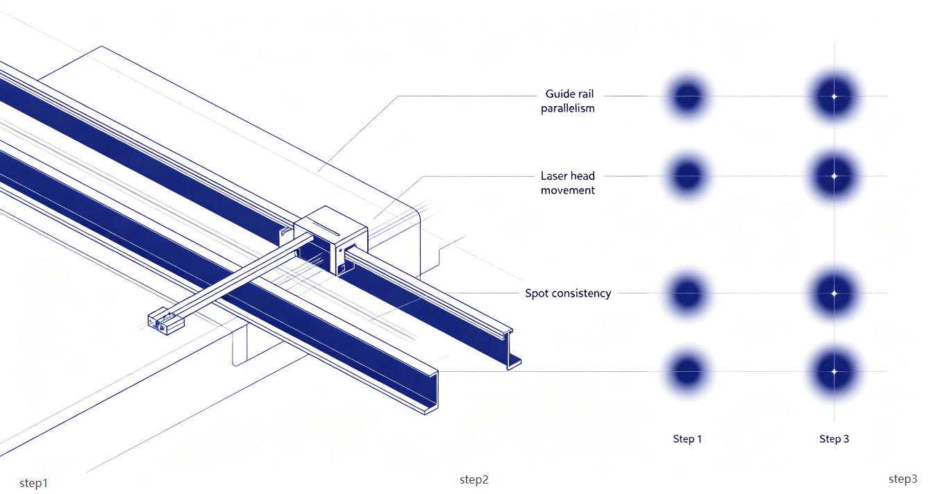
When correcting the parallelism of the two axis rails, use the laser to irradiate along the axis direction until the spots at both ends of the axis are consistent.
Then move the laser head to the proximal end of the axis and irradiate along the axis direction again. Check whether the spots at the remote end and the proximal end of the X-axis are aligned vertically.
Next, check whether the spot in the lower right corner is consistent with the other three spots in the vertical direction.
Correction Steps:
- If the lower-right spot is low, loosen the screws between the aluminum profile and the fixing block below the left guide rail.
- Add small iron sheets between the aluminum profile and the fixing block at the lower-left corner to raise the aluminum profile slightly.
- Tighten the screws.
- Repeat the above steps to check whether the four spots are consistent.
- If the spot is still low, continue adding small iron sheets and readjust until all four spots are vertically consistent.
2. Worktable Level Correction
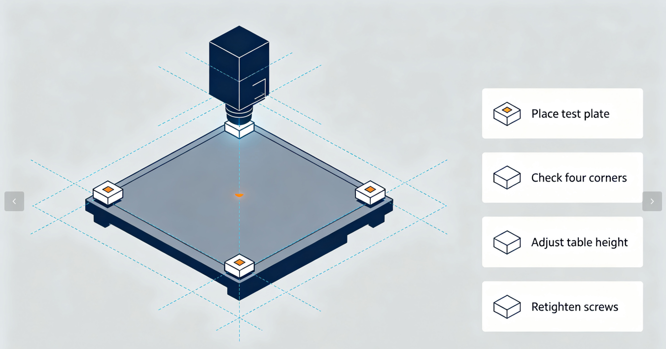
Place a plate on the worktable, with a size approximately the same as the table surface. Then place a small square gauge of about 5 mm on the plate.
Correction Steps:
- Move the laser head to one corner of the table.
- Move the nozzle up and down until it touches the surface of the small square gauge.
- Move the laser head to the other three corners and use the small square gauge to test the distance between the nozzle and the plate at each position.
- Find the lowest corner and use it as the reference point.
- Loosen the screws on the fixed tabletop.
- Slowly tap the tabletop downward at the screw position.
- Move the laser head to that position again and test the height with the small square gauge.
- Continue tapping and testing until the height is consistent with the reference point.
- Move the laser head to other positions and repeat the adjustment.
- When the height of the entire tabletop is consistent with the reference point, tighten all fixing screws.
3. Squareness & Diagonal Calibration
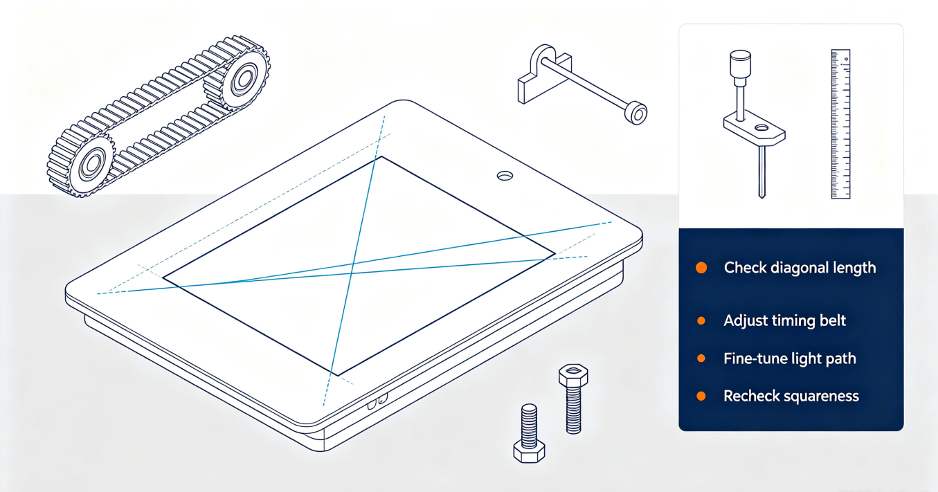
Cut a rectangle approximately the size of the table on a flat plate or cardboard.
- Line A: from the top-right corner to the bottom-left corner
- Line B: from the top-left corner to the bottom-right corner
Use line B as the reference:
Correction Steps:
- If the length of line A differs by more than 3 mm, adjust the corresponding belt teeth to make the horizontal direction skew downward slightly.
- Tighten the belt.
- Adjust the light path until the difference is close to 3 mm.
- Loosen the adjustment lever at the upper end of the right Y-axis synchronous belt.
- Lock the screws on the lower adjustment lever.
- Fine-tune the light path.
- Repeat several times until the diagonal accuracy meets the requirement.
Final Suggestion
Mechanical correction is the basis for stable cutting quality. When burrs, hole deformation, abnormal sparks or unstable cutting accuracy occur, it is recommended to check the guide rail parallelism, table level and squareness first, and then adjust laser parameters accordingly.
